TCS34725 Color Sensor Report

TCS34725 Color Sensor

Introduction
For this report I investigated the TCS34725 Color Sensor. Typically passive sensors, one that measures values from the environment, are not tangible. The goal of this report is to consider using a color sensor within a larger system for a tangible interaction.

Description
The TCS34725 is a light (analog) to digital converter. More specifically it measures four channels of light. The typical red green blue in addition to a clear light which measures the lux. Lux is a unit for illuminance over an area.
It also contains an IR filter, to help the sensor read what humans actually see.

In the breakout board version from Adafruit, a white light LED illuminator is installed. This helps get “accurate” or more consistent color readings when the ambient light is not a controlled variable.

Data Sheet
These are the datasheets from AMS and Adafruit:
Manufacturer’s Data Sheet – AMS
Breakout Board Datasheet – Adafruit
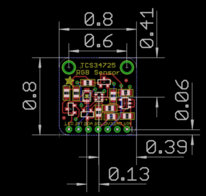

Key Features

  • Integrated IR blocking filter
  • 3.8M:1 dynamic range
  • Four independent analog-to-digital converters
  • A reference-channel for Color Analysis (Clear channel photo-diode)

Key Benefits

  • Minimizes IR and UV spectral component effects to produce accurate color measurement
  • Enables accurate color and ambient light sensing under varying lighting conditions
  • Minimizes motion / transient errors
  • Clear-Channel provides a reference allows for isolation of color content

Soldering
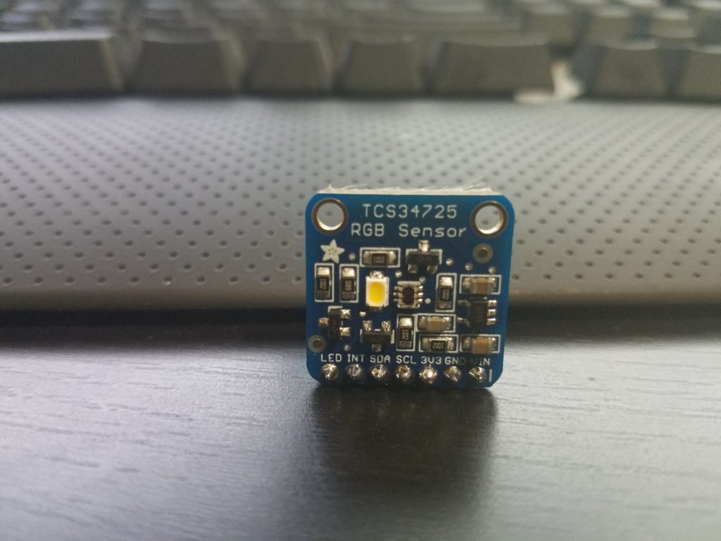
The process for soldering the board is standard. Typically you are given a row of pins that is one too long. Break one pin off and place the rest (connected) in a bread board. If you put the board on the pins you may notice it leans on the other side. You can use the extra pin to prop up the opposite side through the mounting hole.

Since the spacing is close, I would recommend testing for shorts with your multi-meter.

Library
Within the Arduino IDE you can use the wizard to install the TCS34725’s library. Search for TCS34725.
You can manually obtain the files here: Adafruit TCS34725 Library

Findings
It is relatively easy to get the circuit working. The complexity is introduced based on your application and fine tuning. Some of the concerns I have when working with this passive sensor are the speed and precision.

Ways to get around the limits of an individual sensor, assuming that’s where the bottle neck is occurring, is to increase the amount of sensors and/or microcontrollers in your project. Somes ways to accomplish this is with multiplexing or creative coding or using brute force. Some sensors behave better than others in groups. These sensors have a static I2C address, and that will cause issues unless you multiplex physically or through code.

For this color sensor, the exposure time affects the brightness read. This is controlled by a variable:  TCS34725_INTEGRATIONTIME_50MS.
50MS is the exposure time for the reading. All other things being the same, lowering the exposure time reduces the values or intensity of the RGBC readings.

If you want the current exposure time but twice the rate of readings, you may consider introducing a second sensor. You can keep them on pace by assigning them to the rise and fall of the clock cycle. I have not tested this for these chips though.  However the speed of these sensors would not work well with most speed dependent applications like video games and instruments.

Example Uses
Some uses for these color sensors are color testing output of color reprographics devices. In fact color testing in general would be a obvious strong point for this sensor, from paint jobs to adjusting light based on the current ambient level.

As far as tangible applications. One could design a device that requires users to insert objects into it. So inserting different colored key cards to be read by the scanner can trigger different events. The enclosure would minimize the amount of light bleed from the environment and the on board illuminator would allow for the color to be read inside.

Another tangible example would be to use the sensors as a “conductor”. What I mean by that is, if you have a translucent enclosure and want to have no visible wires between a button and an open section. You can have a grid of buttons with LEDs that correspond to a unique color for each. Rather than having 18+ wires for a 3×3 grid going through the enclosure. You can mount a color sensor on the opposite end and have it determine the button press based on the color of each one.

Strength and Weaknesses
Strengths

  • Reads RGBC values individually
  • Filters IR light so the values read are closer to actual human sight
  • Relatively low power draw.  Scaling potential.
    • Active = (235 – 330μA)
    • Waiting = (65 μA)
    • Sleep = (2.5 – 10μA)

Weaknesses

  • Small effective range. Up to 4 inches.
  • Relatively slow. Speed affects quality of reading.
  • Static I2C addresses.

Example Circuit Schematic
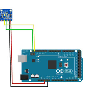
Microcontroller Code

Citations:
Adafruit TCS34725 Library
Breakout Board Fabrication Print

Manufacturer’s Product Site – AMS

Splitter Glove – MIDI Controller (in progress)

The second project for Tangible Interactions was to create a MIDI controller.
I was in NIME last semester and created a final project which was a MIDI controller. The controls were very much intangible, which I partially addressed somewhat in its design. However the controller had a bit more to go to reach my final vision. I wanted to move beyond the limits of the technical flashlights and LEDs I initially used to play it.

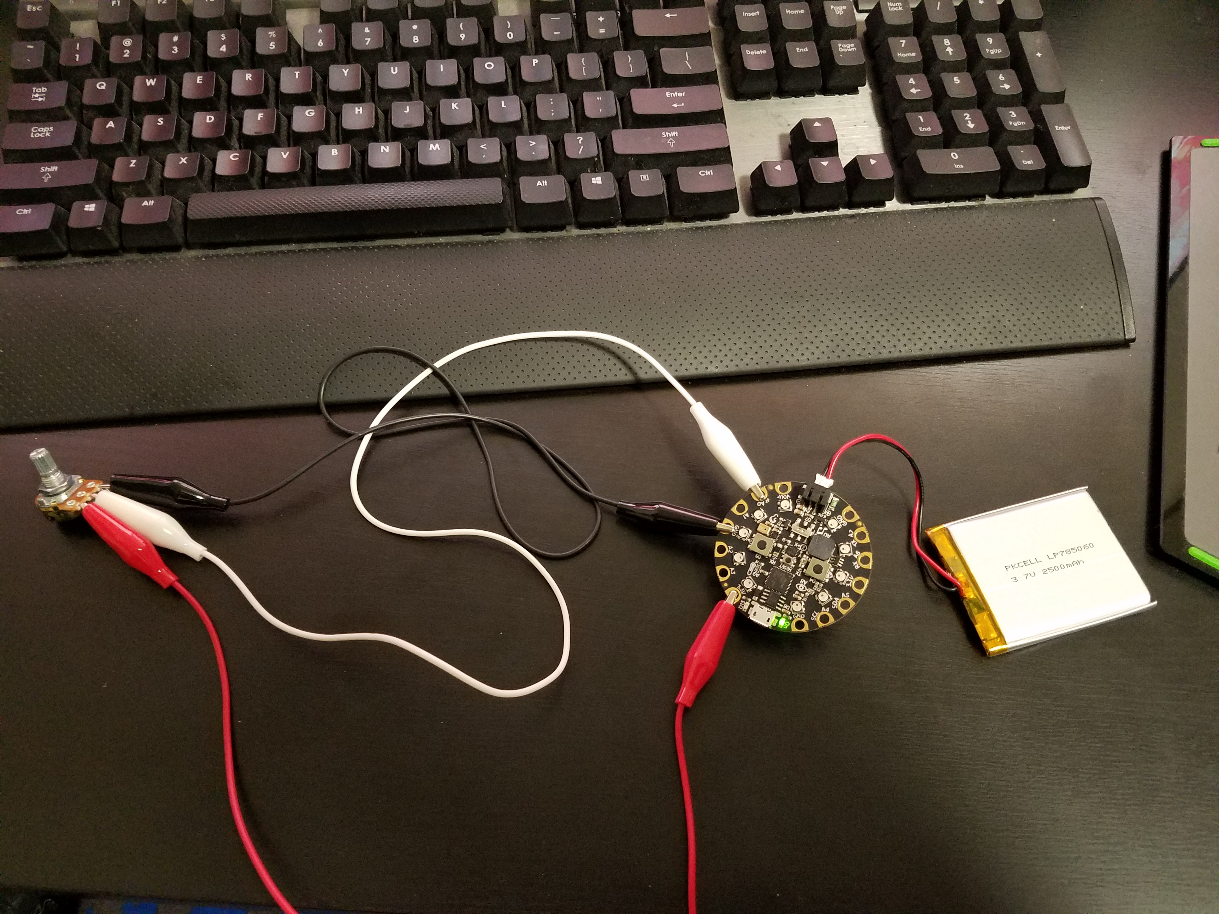
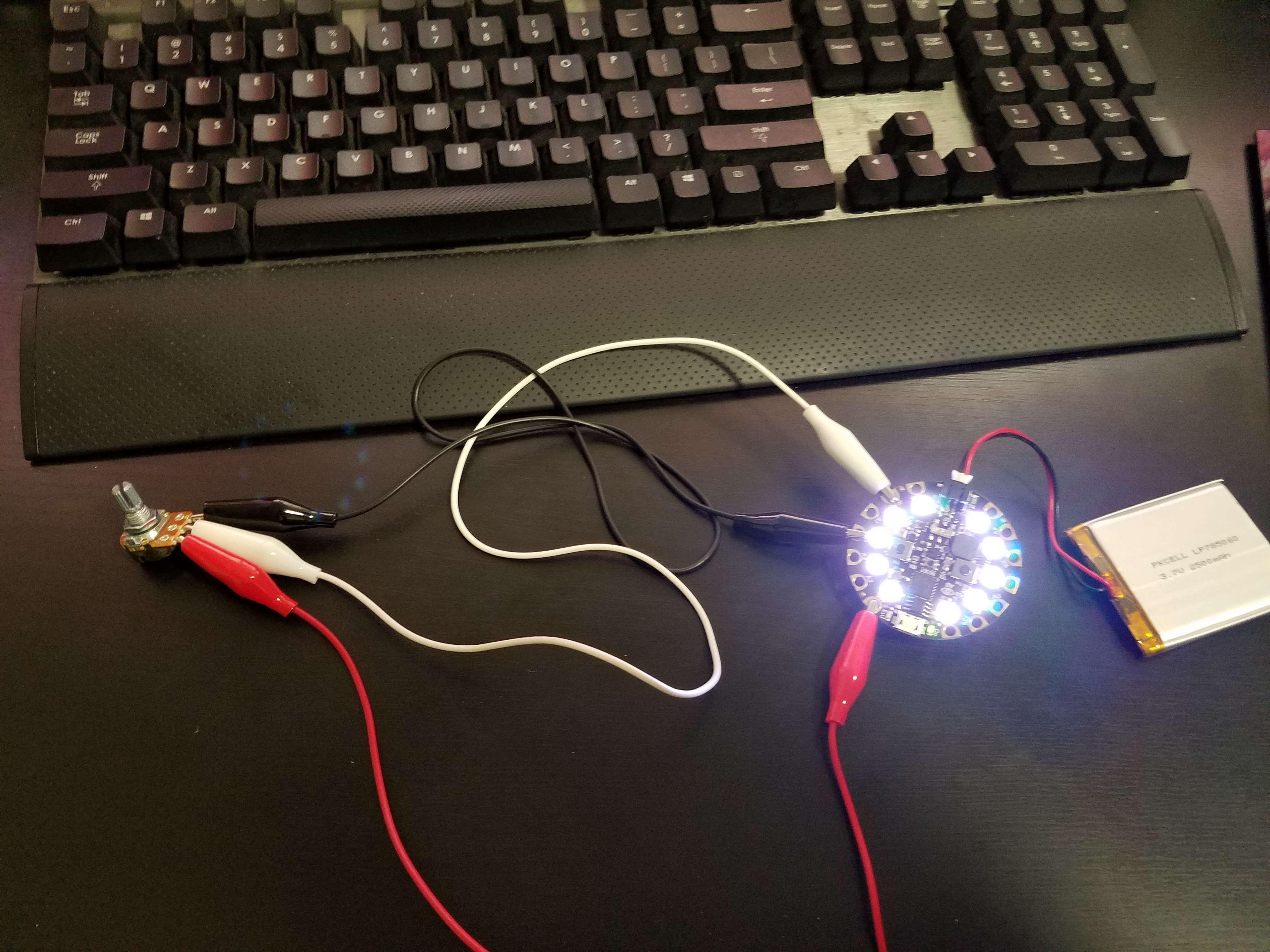
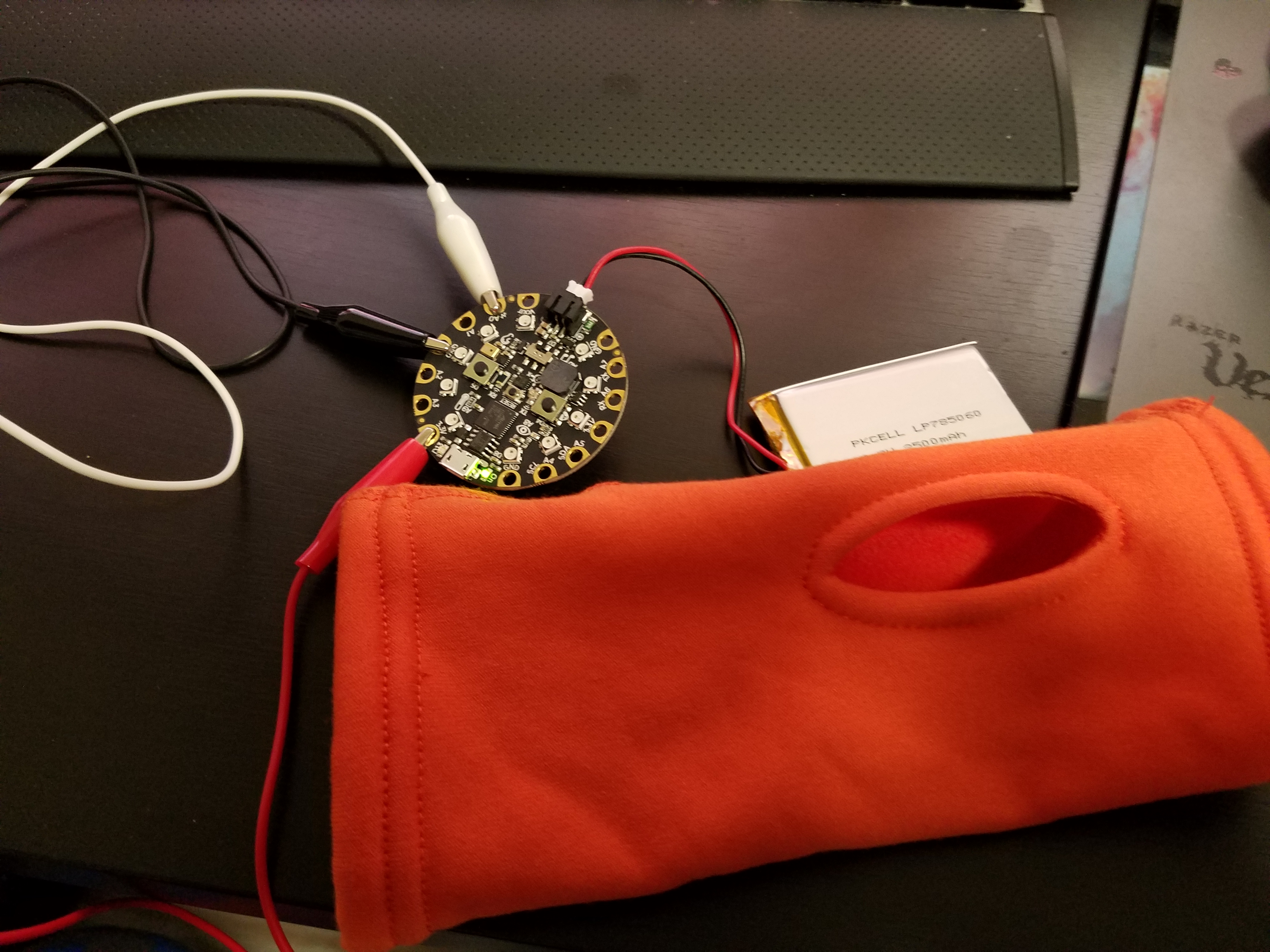
My goal was to add tangible elements to the controller’s interface by using wearable lights and a physical control for the blinking and on/off functionality. The MIDI notes are triggered when light hits the sensor and off when the light level falls below a threshold value. By being able to control the blink rate with a potentiometer, I added a tangible element to an intangible interface.

There are more thing I could modify to increase the preciseness of the controller.  But I have to consider how I want it the experience to evolve.

Synthetic Architecture 02 – Anatomy of Space

I picked waiting as my simulation experience. As humans we are accustomed to things happening in our lifetime. However nature doesn’t conform to our notions of immediacy.

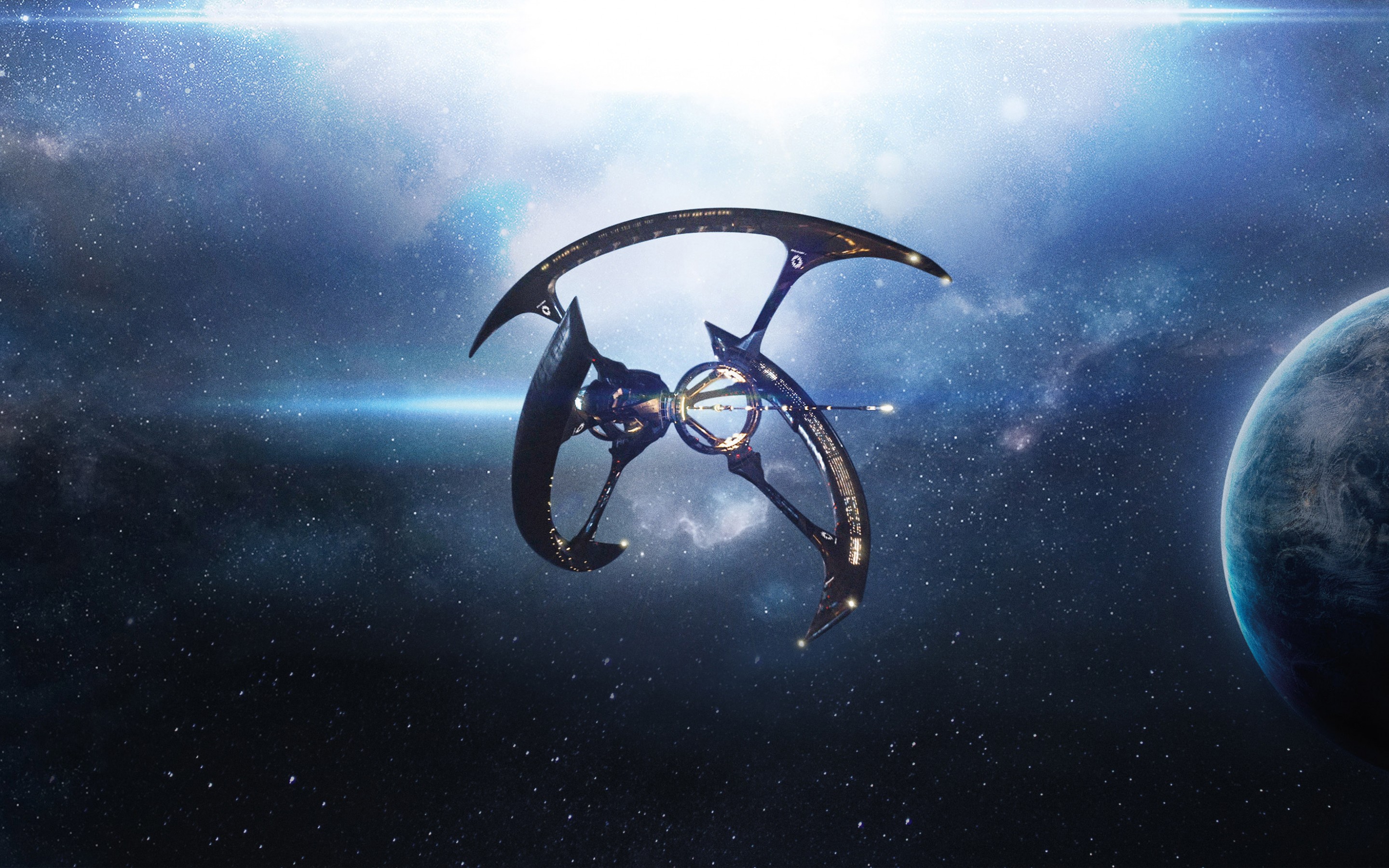
I decided to demonstrate waiting by creating a simulation of travelling through space. The scale would be extreme because the user will not have much interactions in the confined space. As a juxtaposition there will be astronomical events occurring at a great distance visible to the user.


Worlds On A Wire – HW Week 02

For this assignment I jumped into Steam with my Oculus Rift headset, which is a really great and new feature Valve decided to add. I think it’s akin to them adding native support for the Sony Dualshock 4 controller. They have been more inclusive with their platform over the last couple of years.

The experience in the Lab was great. Everything looked better then when I first tried it 2 years ago for some reason. As I mentioned in the previous post, being able to focus at home adds a lot to the immersive experience. I have to say even doing the Steam tutorial, I forgot how to “travel.” So I was stuck in the opening Lab scene for a while.., even after I teleported once. I didn’t realize it was not so rigid and I could teleport again in the same region to get closer to the orb.

As for the Unreal hero shots. I have been combining shapes and assets together. It did take me a while to figure out the importing assets workflow. I feel really restricted in the UE environment. The pain points for me is the navigation of the view port, the snapping of values and not being able to “model geometry” at a higher level that I’m used to. A part of it is learning their modeling tools more. But I have to say I am enjoying the UE interface.

For my scene I created a flat world with shapes and objects. I think it resembles some sort of ruins. The main character is the ice elemental guy.

Worlds On A Wire – Week 01 HW

For our first assignment, Todd asked us to get ourselves acquainted with VR and post our thoughts. I haven’t had much VR experience. I’ve tried Oculus Rift and google cardboard for a few minutes in the past and it was fun.

So now here we are in 2018. Some things have changed since last year, and there’s newer products coming on the horizon. Since I’m taking two VR related courses this year I decided to invest in a VR headset. I am glad I did. With my full time work schedule I needed one that was accessible for me when I had free time.

I ended up getting the Rift. The experience in the privacy of my home was much greater than in school. I had time to appreciate the content and I could hear things very clearly. I had time to forget I was home and engage with the worlds.

I would have to say Google Earth was my favorite experience we were asked to play. When it started I felt like I was in a planetarium. In fact this was better than the Hayden Planetarium because when I was a kid the projection didn’t look as good as this. The interface was clumsy, but being able to fly around and stalk your home in 3D was really awesome.

Dear Angelica was visually engaging and I appreciated the unique rendering style of it. They used scale and colors well and I felt inspired to inspect the scenes as they occurred. Henry was cute, but seemed a bit rough as far as the narrative. The world was nicely rendered, but it became too long and predictable as it progressed.

Honorable mention for the Oculus start up scene. It was a great way to get adjusted to the controls. I felt like I was really playing with the disks and rockets. The retro feel spoke to me as a kid of the 80’s.


Game Controller Assignment (HID USB)

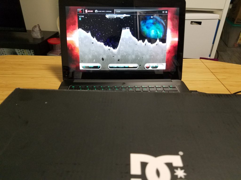
For our first assignment for Tangible Interaction involved creating a controller for Lunar Lander. I decided to mimic the arcade control layout of similar games like Asteroids. Each action has a dedicated button and both hands were used. I tried both versions of Lunar Lander and felt the Atari remaster was more enjoyable for me. I thought it also would be fun to be able to switch between mouse and keyboard input.

In space you have to be resourceful.

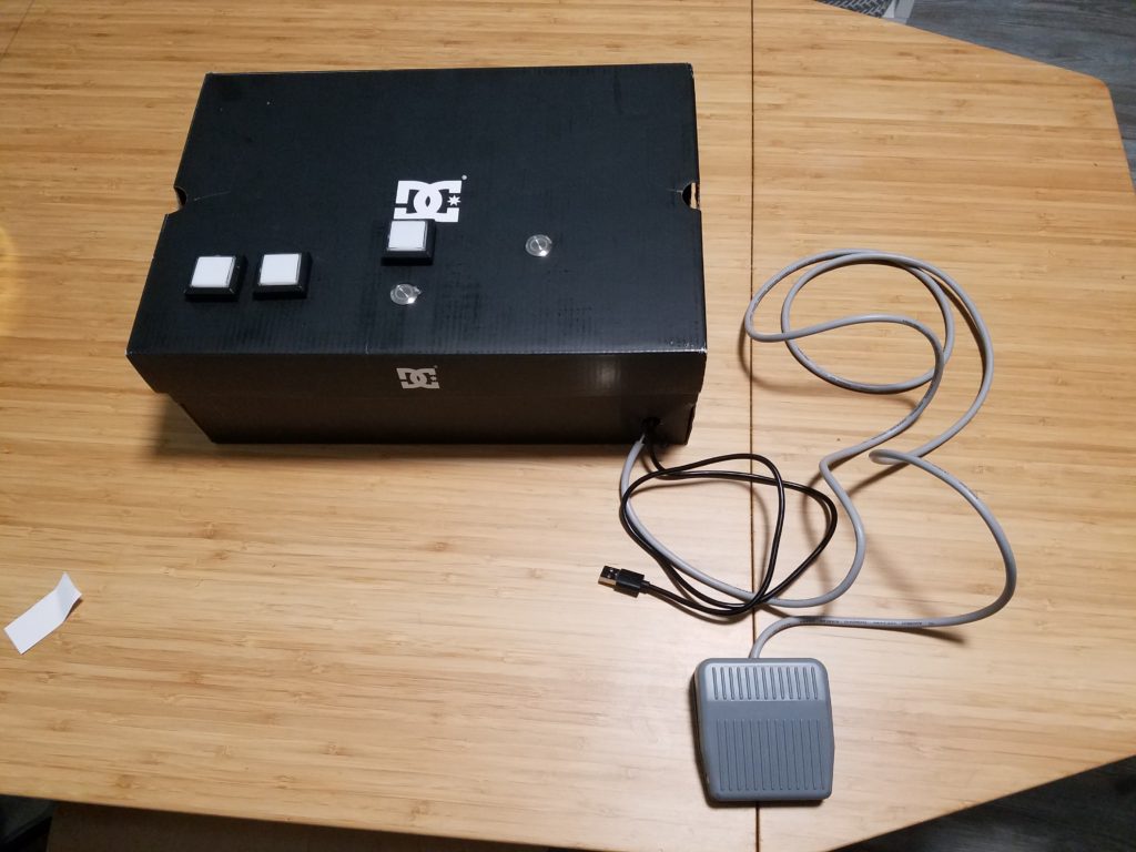
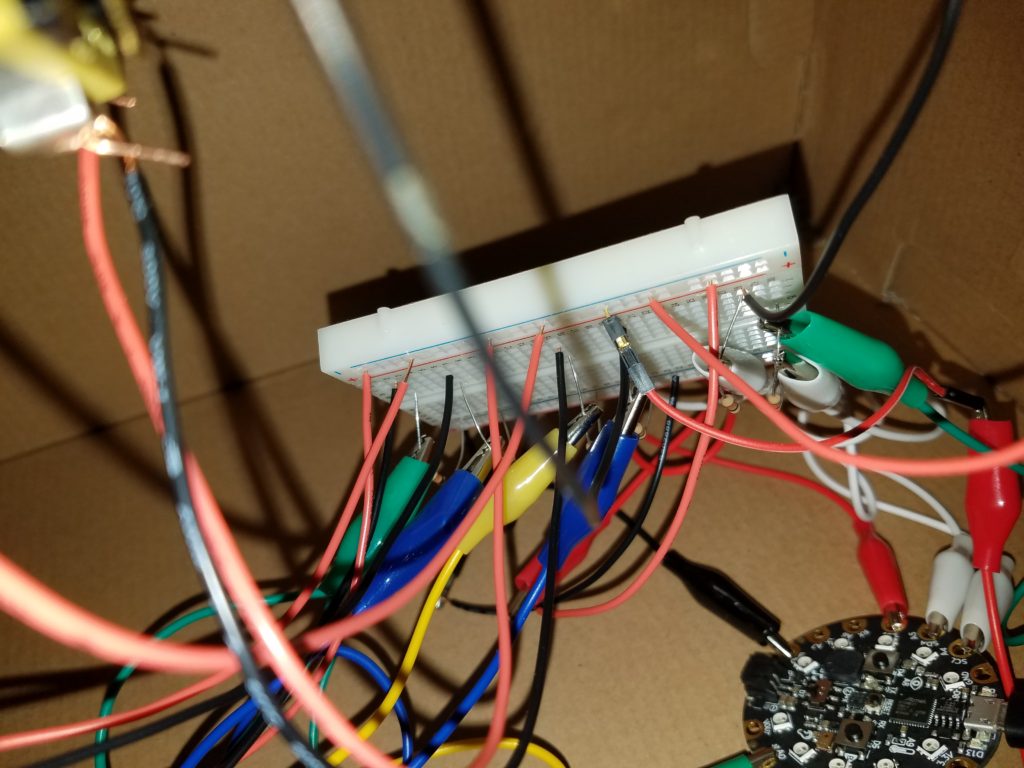
This would have crashed Elon Musk’s rocket. There’s an Circuit Playground express connected to a breadboard as a hub and then plenty of buttons.

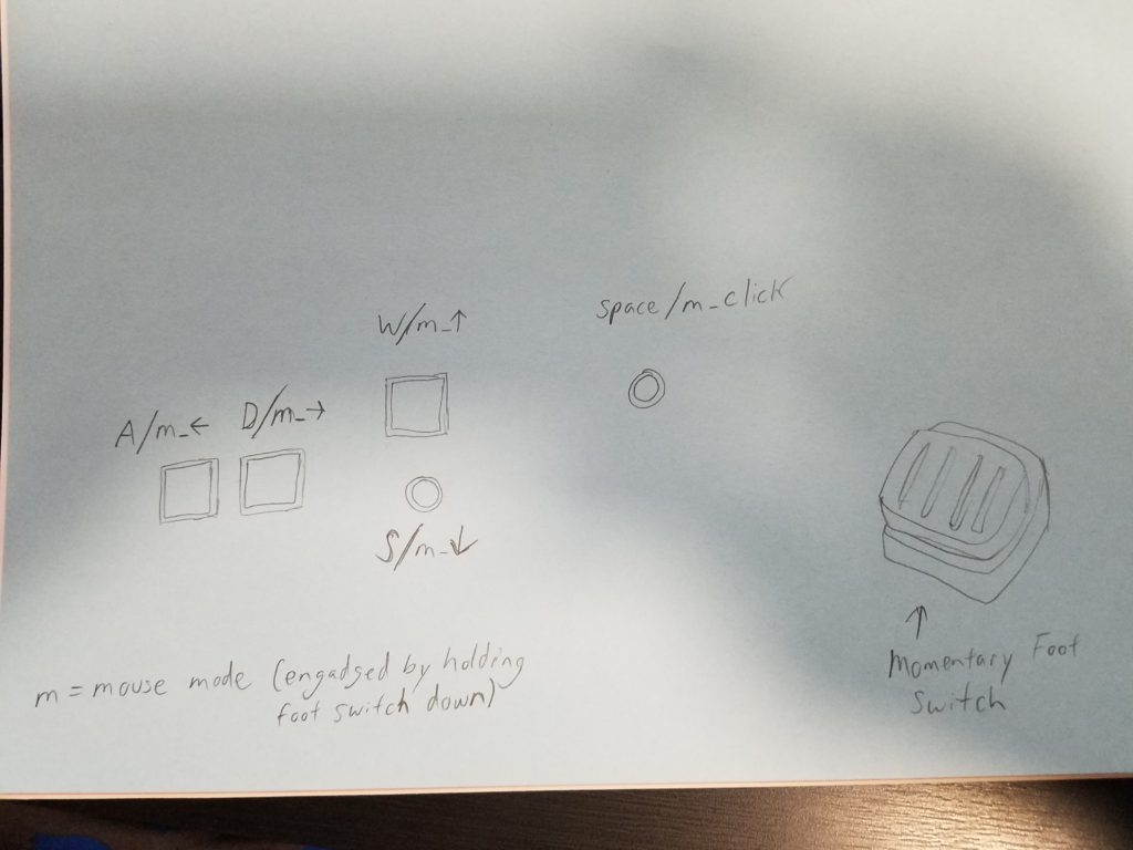
This is the controller layout with dual function buttons.

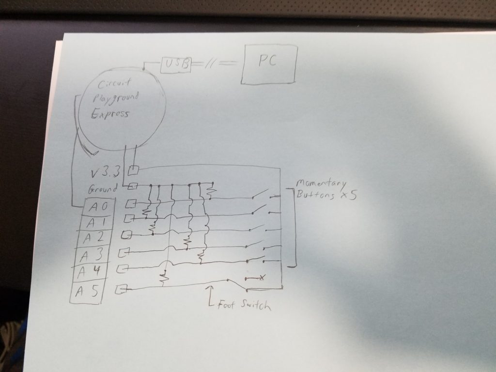
Relatively straightforward schematic. There are 6 momentary buttons.

To accommodate having a controller switch between keyboard and mouse output, I created a dedicated button controlled by the players foot. This allowed the player to start the game which required the mouse input and then to immediately jump into ship mode by releasing their foot.

SOURCE CODE

#include <Keyboard.h>
#include <Mouse.h>

//Button to Pin assignments
const int upButton = A0;
const int downButton = A1;
const int leftButton = A2;
const int rightButton = A3;
const int mouseButton = A4;
const int altButton = A5;
//Modifier button
int altSwitch = 0;
int prevSwitch = 0;

int range = 5;
int responseDelay = 10;

void setup() {
pinMode(upButton, INPUT_PULLUP); //Arduino reads pin 3 as input
pinMode(downButton, INPUT_PULLUP);
pinMode(leftButton, INPUT_PULLUP);
pinMode(rightButton, INPUT_PULLUP);
pinMode(mouseButton, INPUT_PULLUP);
pinMode(altButton, INPUT_PULLUP);

Serial.begin(9600);
Keyboard.begin();
Mouse.begin();
}

void loop() {

if (digitalRead(altButton) == HIGH){
int rightState = digitalRead(upButton);
int leftState = digitalRead(downButton);
int upState = digitalRead(rightButton);
int downState = digitalRead(leftButton);
int clickState = digitalRead(mouseButton);

// calculate the movement distance based on the button states:
int xDistance = (leftState – rightState) * range;
int yDistance = (upState – downState) * range;

// if X or Y is non-zero, move:
if ((xDistance != 0) || (yDistance != 0)) {
Mouse.move(xDistance, yDistance, 0);
}

// if the mouse button is pressed:
if (clickState == HIGH) {
// if the mouse is not pressed, press it:
if (!Mouse.isPressed(MOUSE_LEFT)) {
Mouse.press(MOUSE_LEFT);
}
}
// else the mouse button is not pressed:
else {
// if the mouse is pressed, release it:
if (Mouse.isPressed(MOUSE_LEFT)) {
Mouse.release(MOUSE_LEFT);
}
}

delay(responseDelay);
} //end if statement (altSwitch == 0){

if (digitalRead(altButton) == LOW){
if (digitalRead(upButton) == HIGH) {
Keyboard.write(‘a’);
}
if (digitalRead(downButton) == HIGH) {
Keyboard.write(‘d’);
}
if (digitalRead(leftButton) == HIGH) {
Keyboard.write(‘w’);
}
if (digitalRead(rightButton) == HIGH) {
Keyboard.write(‘s’);
}
if (digitalRead(mouseButton) == HIGH) {
Keyboard.write(32);
}
}//end if altswitch = 1;
}

In my code I referenced and modified code available from:
https://www.arduino.cc/reference/en/language/functions/usb/keyboard/

https://www.arduino.cc/reference/en/language/functions/usb/keyboard/keyboardmodifiers/