TCS34725 Color Sensor Report

TCS34725 Color Sensor

Introduction
For this report I investigated the TCS34725 Color Sensor. Typically passive sensors, one that measures values from the environment, are not tangible. The goal of this report is to consider using a color sensor within a larger system for a tangible interaction.

Description
The TCS34725 is a light (analog) to digital converter. More specifically it measures four channels of light. The typical red green blue in addition to a clear light which measures the lux. Lux is a unit for illuminance over an area.
It also contains an IR filter, to help the sensor read what humans actually see.

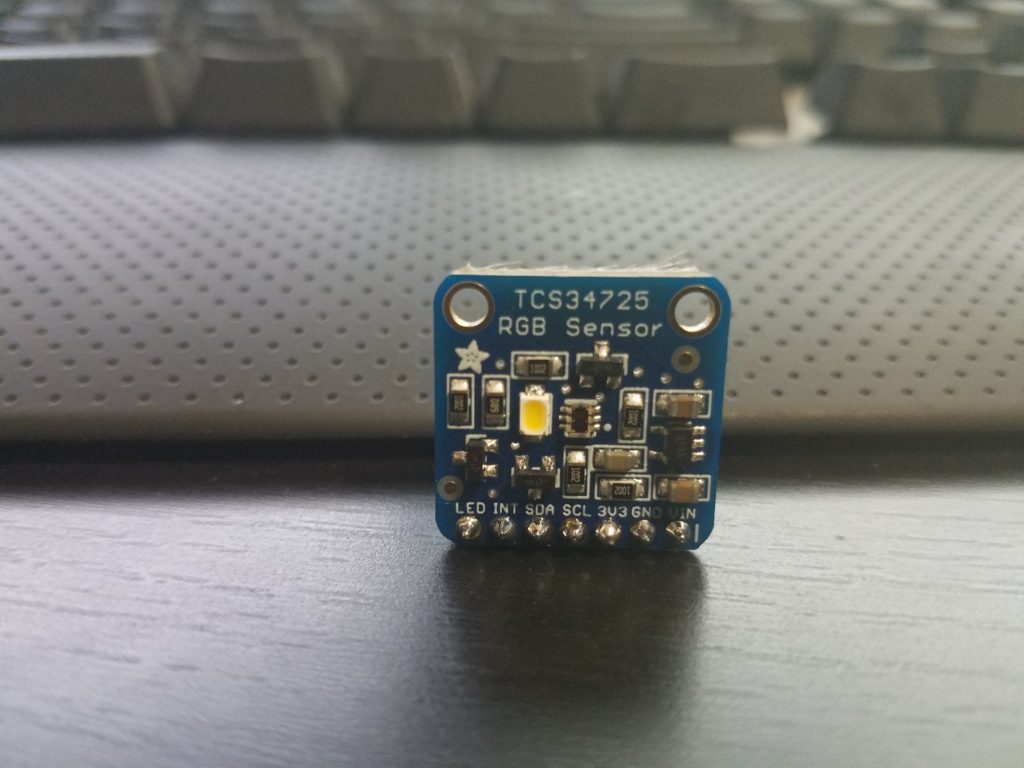
In the breakout board version from Adafruit, a white light LED illuminator is installed. This helps get “accurate” or more consistent color readings when the ambient light is not a controlled variable.

Data Sheet
These are the datasheets from AMS and Adafruit:
Manufacturer’s Data Sheet – AMS
Breakout Board Datasheet – Adafruit


Key Features

  • Integrated IR blocking filter
  • 3.8M:1 dynamic range
  • Four independent analog-to-digital converters
  • A reference-channel for Color Analysis (Clear channel photo-diode)

Key Benefits

  • Minimizes IR and UV spectral component effects to produce accurate color measurement
  • Enables accurate color and ambient light sensing under varying lighting conditions
  • Minimizes motion / transient errors
  • Clear-Channel provides a reference allows for isolation of color content

Soldering

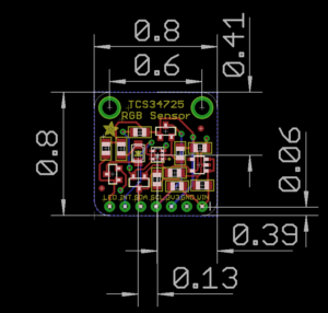
The process for soldering the board is standard. Typically you are given a row of pins that is one too long. Break one pin off and place the rest (connected) in a bread board. If you put the board on the pins you may notice it leans on the other side. You can use the extra pin to prop up the opposite side through the mounting hole.

Since the spacing is close, I would recommend testing for shorts with your multi-meter.

Library
Within the Arduino IDE you can use the wizard to install the TCS34725’s library. Search for TCS34725.
You can manually obtain the files here: Adafruit TCS34725 Library

Findings
It is relatively easy to get the circuit working. The complexity is introduced based on your application and fine tuning. Some of the concerns I have when working with this passive sensor are the speed and precision.

Ways to get around the limits of an individual sensor, assuming that’s where the bottle neck is occurring, is to increase the amount of sensors and/or microcontrollers in your project. Somes ways to accomplish this is with multiplexing or creative coding or using brute force. Some sensors behave better than others in groups. These sensors have a static I2C address, and that will cause issues unless you multiplex physically or through code.

For this color sensor, the exposure time affects the brightness read. This is controlled by a variable:  TCS34725_INTEGRATIONTIME_50MS.
50MS is the exposure time for the reading. All other things being the same, lowering the exposure time reduces the values or intensity of the RGBC readings.

If you want the current exposure time but twice the rate of readings, you may consider introducing a second sensor. You can keep them on pace by assigning them to the rise and fall of the clock cycle. I have not tested this for these chips though.  However the speed of these sensors would not work well with most speed dependent applications like video games and instruments.

Example Uses
Some uses for these color sensors are color testing output of color reprographics devices. In fact color testing in general would be a obvious strong point for this sensor, from paint jobs to adjusting light based on the current ambient level.

As far as tangible applications. One could design a device that requires users to insert objects into it. So inserting different colored key cards to be read by the scanner can trigger different events. The enclosure would minimize the amount of light bleed from the environment and the on board illuminator would allow for the color to be read inside.

Another tangible example would be to use the sensors as a “conductor”. What I mean by that is, if you have a translucent enclosure and want to have no visible wires between a button and an open section. You can have a grid of buttons with LEDs that correspond to a unique color for each. Rather than having 18+ wires for a 3×3 grid going through the enclosure. You can mount a color sensor on the opposite end and have it determine the button press based on the color of each one.

Strength and Weaknesses
Strengths

  • Reads RGBC values individually
  • Filters IR light so the values read are closer to actual human sight
  • Relatively low power draw.  Scaling potential.
    • Active = (235 – 330μA)
    • Waiting = (65 μA)
    • Sleep = (2.5 – 10μA)

Weaknesses

  • Small effective range. Up to 4 inches.
  • Relatively slow. Speed affects quality of reading.
  • Static I2C addresses.

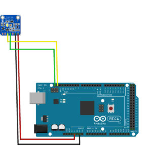
Example Circuit Schematic

Microcontroller Code

Citations:
Adafruit TCS34725 Library

Breakout Board Fabrication Print

Manufacturer’s Product Site – AMS

Final Project

My final project proposal is derived off of my previous work. Continuing with the theme of modifying user submitted images, I decided to do an experiment with generating ID cards.

A user would enter in relevant information like name and year, then choose a school’s ID format. Lastly they would upload a picture to use for the ID and they would receive back a generated image similar to the ID they would have as a student of that school.

This is for intellectual purposes only. I feel depending on Visual ID checks is a big vulnerability for any institution.

Winter Show 2016

I did a Hail Mary play and a complete gamble by ordering some uber IR sensors on Friday, having same day delivery for $30 with no idea if these will work how it needed to. The gamble paid off, and while I am poorer for it, we were able to have a better functioning sensor array for the show.
Though that was just one of many hurdles we faced before and during the Winter Show including Melissa building up a chassis we consulted with Chester on. Melissa and I had an awesome time even though we were a bit stressed with all the tinkering we needed to do to ‘right’ the ship.We were approached by some interested people who will pay us half a billion dollars to make it for their bathrooms!!

Videos soon.

Final Project Pre-Show Update


The third prototype:
For our final physical computing class, we really wanted to get four sensors working. Unfortunately the delays that we used to send and receive ultrasonic pings clogged up the entire system. The current state of our code only allows for two sensors. However, we made progress in terms of getting one sensor to play multiple notes, as seen in this video:

[youtube https://www.youtube.com/watch?v=Mh-9GeeujMs&w=560&h=315]

We’re still not sure the best way to “zhush” it up, other than by adding painting the pvc pipe? We still need to figure out the kind of enclosure we want to use for our circuit, and bring some dignity to the sad plastic basin. We also need to get a working system without using four different arduinos. But the prototype works!

Final Project Update

STATUS UPDATE:
Melissa and I ran some more tests with lasers and water streams at school and individually at home. Unfortunately we are still fine tuning our alternative light and sensor interface that will trigger the MIDI notes.

circuit-one-note
This is our first attempt at a MIDI output circuit.

[youtube https://www.youtube.com/watch?v=S9DfrA_zg9s]
This is us using the stock MIDI code from Arduino’s site. We are running the Arduino through a MIDI jack to a MIDI/USB converter and then into a soft synth.

[youtube https://www.youtube.com/watch?v=N_N5kUX2LUY]
This is one of our laser tests. I think it’s a cool effect but if we do use it, it will be more for aesthetic purposes.

We met again yesterday to test out our pump and PVC pipes for the fabrication part of the project. I think we are in a good place but we still have to catch up on the deliverables. Luckily I took off next week to focus on getting this completed.

DELIVERABLES (in progress):

Concept & Brainstorming (DRAFT)

Melissa and I decided to work together for the final project. We are working on creating a water instrument. The main interface will be a water fall or water sheet.20161110_111227

I am thinking about the pros and cons or it being a midi controller versus a function generator.

+Post Final Project Concept discussion (11/12/16):
We had a very productive demonstration of our water synth project. Here is a video of how we simulated our concept.
[youtube https://www.youtube.com/watch?v=SwhLLJ6mam0]

We received a lot of great feedback from our classmates and of course our Instructor Benedetta. After the testing we knew we had a good idea to proceed with and were confident that it would be something we could pursue.

After the demo we met to test our idea. We wanted to have several lasers travel through a waterfall. Unfortunately that is not easy to do and the results were not promising. We were able to get the laser to travel along a stream but it became increasingly difficult to get a projection the higher we went.

DELIVERABLES (WIP)

Proposals for Final Project

I enjoy listening to and playing synthesizers. These days most synthesizers are digital. That’s great because it allows them to be cheaper and reach a greater amount of people while offering a greater flexibility with sound. However there’s a limit to the resolution of digital synthesizers. We also lose a lot from circuits that simulate or model an analog synth. Analog synths are expensive, they’re messy, heavy etc.

1- One idea for a final is to bring analog qualities back into sampled and function generated wave forms. Usually water and synthesizers don’t mix. But if I can run a MIDI controller through a circuit that uses a water height sensor, I think I would be able to add back analog elements into the sounds being played. Also maybe the water can be the expression interface for the instrument itself. I can use other physical qualities of water to manipulate sound and modulation.

proposal-for-final

2- A second idea I had was to detect position along a RGB plane and have that affect color output among other things. There are already MIDI controllers that allow sound modulation along track pad axis. However this could be an interesting project if there is a unique application for it.


Midterm

For our PComp midterm everyone in my class was assigned into groups to work on a project. I initially thought it would be a good idea to use a sensor array to map out a color space and have the output reflect where the user was activating. We ran into some issues with the microphone behavior so we decided to re-purpose our configuration for another interaction.

We ended up making the interaction be based on sound and distance. We mapped 3 sensors to a corresponding color value. We had each color go to 3 LEDs in series. Our idea was that we could get the colors to blend if we diffuse them at a distance.

One of the biggest problems we ran into was dealing with the noise of the environment and the circuit. We couldn’t get the sensor readings to zero or even close to it. So we ended up having to deal with low resolution values for our sensor range.

This is the proof of concept. Using one microphone to control the brightness of the LED.
image5

We then expanded the concept to 3 microphone sensors.
image3

image4

We at the same time wanted to work on the serial communication with P5. We ran into some additional issues here. Most of which probably involved us not using a handshake for communication.

image2

[youtube https://www.youtube.com/watch?v=6a4Kj3TGMXg]

[youtube https://www.youtube.com/watch?v=zl_HptopmWU]

[youtube https://www.youtube.com/watch?v=z2RA5YnfFWI]

Serial Communication Labs 10/22/16

I first worked on the Async serial communication lab. This went fairly well. I didn’t use the accelerometer because I haven’t soldered the contacts yet. Instead I used 2 variable resistors as seen in the pic.

20161021_202857

20161021_204214

I then tried my first attempt at P5 and it was a mess. I tried following along with the directions, but the index.html file didn’t have the line that was referenced. “script language=”javascript” type=”text/javascript” src=”libraries/p5.js”></script”.

I ended up pasting both lines in it. The add file function doesn’t seem to work for me so after a blank file was added, I pasted the contents of the p5.serialport.js inside it.

At some point I was able to find out my serial port name but I can’t seem to open it properly at this point. I am showing the error below. I’ll need to ask for help getting this running.

20161022_212600