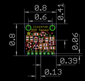
TCS34725 Color Sensor
Introduction
For this report I investigated the TCS34725 Color Sensor. Typically passive sensors, one that measures values from the environment, are not tangible. The goal of this report is to consider using a color sensor within a larger system for a tangible interaction.
Description
The TCS34725 is a light (analog) to digital converter. More specifically it measures four channels of light. The typical red green blue in addition to a clear light which measures the lux. Lux is a unit for illuminance over an area.
It also contains an IR filter, to help the sensor read what humans actually see.
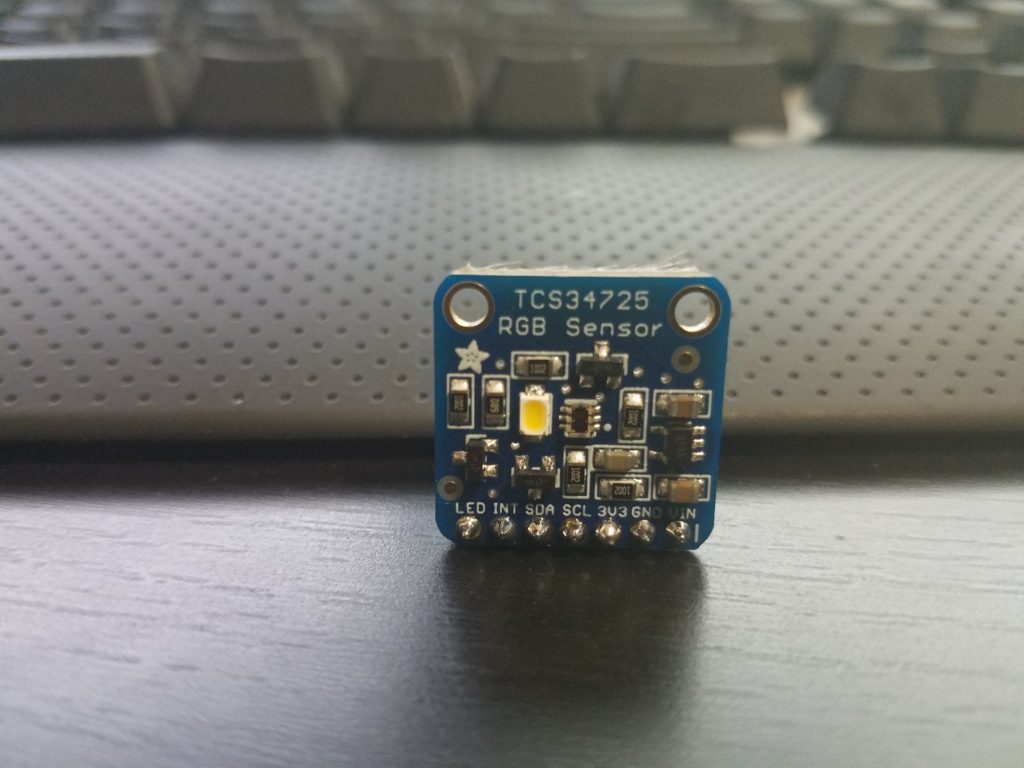
In the breakout board version from Adafruit, a white light LED illuminator is installed. This helps get “accurate” or more consistent color readings when the ambient light is not a controlled variable.
Data Sheet
These are the datasheets from AMS and Adafruit:
Manufacturer’s Data Sheet – AMS
Breakout Board Datasheet – Adafruit

Key Features
- Integrated IR blocking filter
- 3.8M:1 dynamic range
- Four independent analog-to-digital converters
- A reference-channel for Color Analysis (Clear channel photo-diode)
Key Benefits
- Minimizes IR and UV spectral component effects to produce accurate color measurement
- Enables accurate color and ambient light sensing under varying lighting conditions
- Minimizes motion / transient errors
- Clear-Channel provides a reference allows for isolation of color content
Soldering

The process for soldering the board is standard. Typically you are given a row of pins that is one too long. Break one pin off and place the rest (connected) in a bread board. If you put the board on the pins you may notice it leans on the other side. You can use the extra pin to prop up the opposite side through the mounting hole.
Since the spacing is close, I would recommend testing for shorts with your multi-meter.
Library
Within the Arduino IDE you can use the wizard to install the TCS34725’s library. Search for TCS34725.
You can manually obtain the files here: Adafruit TCS34725 Library
Findings
It is relatively easy to get the circuit working. The complexity is introduced based on your application and fine tuning. Some of the concerns I have when working with this passive sensor are the speed and precision.
Ways to get around the limits of an individual sensor, assuming that’s where the bottle neck is occurring, is to increase the amount of sensors and/or microcontrollers in your project. Somes ways to accomplish this is with multiplexing or creative coding or using brute force. Some sensors behave better than others in groups. These sensors have a static I2C address, and that will cause issues unless you multiplex physically or through code.
For this color sensor, the exposure time affects the brightness read. This is controlled by a variable: TCS34725_INTEGRATIONTIME_50MS.
50MS is the exposure time for the reading. All other things being the same, lowering the exposure time reduces the values or intensity of the RGBC readings.
If you want the current exposure time but twice the rate of readings, you may consider introducing a second sensor. You can keep them on pace by assigning them to the rise and fall of the clock cycle. I have not tested this for these chips though. However the speed of these sensors would not work well with most speed dependent applications like video games and instruments.
Example Uses
Some uses for these color sensors are color testing output of color reprographics devices. In fact color testing in general would be a obvious strong point for this sensor, from paint jobs to adjusting light based on the current ambient level.
As far as tangible applications. One could design a device that requires users to insert objects into it. So inserting different colored key cards to be read by the scanner can trigger different events. The enclosure would minimize the amount of light bleed from the environment and the on board illuminator would allow for the color to be read inside.
Another tangible example would be to use the sensors as a “conductor”. What I mean by that is, if you have a translucent enclosure and want to have no visible wires between a button and an open section. You can have a grid of buttons with LEDs that correspond to a unique color for each. Rather than having 18+ wires for a 3×3 grid going through the enclosure. You can mount a color sensor on the opposite end and have it determine the button press based on the color of each one.
Strength and Weaknesses
Strengths
- Reads RGBC values individually
- Filters IR light so the values read are closer to actual human sight
- Relatively low power draw. Scaling potential.
- Active = (235 – 330μA)
- Waiting = (65 μA)
- Sleep = (2.5 – 10μA)
Weaknesses
- Small effective range. Up to 4 inches.
- Relatively slow. Speed affects quality of reading.
- Static I2C addresses.
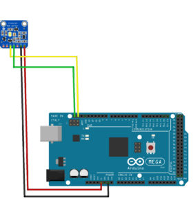
Example Circuit Schematic

Microcontroller Code
Citations:
Adafruit TCS34725 Library