Social Wearables Post #1

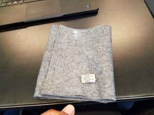
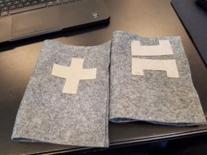
Intro to making social wearables. For the first in class assignment we were tasked with making high five gloves. The purpose of this assignment was to get familiar with working with soft circuits.

My design is based on the example Kate showed us. For the conductive pads I decided to use polygons because I liked the idea of adding sharp edges to pliable materials. I have some sewing experience in the form of patching holes in fabric. It’s definitely a useful skill to have in life.

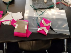
I created a cross design so the circuit could be closed easily from many angles. I didn’t want to use a big square as a switch and a part of the fun is playing with shapes while still getting the gloves to work.

My stitching was messier than I would have liked and one of the threads broke. But otherwise I thought it was successful.

The group project to create a social wearable for a different object was also engaging. We came up with a fist bump knuckles. The function is essentially the same, but the interaction involved connecting fists. I felt these required more attention as fists are more easily rotated so the conductive pads needs to account for that.


World On A Wire Midterm

For my World’s on a Wire midterm I decided to continue some of my previous work with virtual instruments. Before I used Unity to explore deconstructing and playing songs by navigating through an environment via a 3rd person avatar.
This time around I approached this through a VR headset and using Unreal engine. My idea was to trigger different sound elements by throwing objects at targets. My hope was to have the targets indicate they have been triggered not only with a sound clip but also physically by spinning and triggering lights.

Unfortunately this wasn’t a 1 to 1 translation between the two engines. It proved more difficult trying to translate a good experience into VR as well. Here is a demo of my midterm:

I was hoping to have the sound objects spin, but I was not able to combine that in time. To demonstrate the rotation element I created a demo spinner. I would like to tie that with an audio attribute. For example spinning faster can make the sound louder and or speed up or reverse playback. I also knew turning the playback off by hitting the targets again wouldn’t be as easy, so that is another aspect I need to explore.

These interactions can be used for storytelling by being able to explore songs, words or other sounds in “tangible” way.
I think this could be worth exploring for my final time permitting. I found it can be too easy to get distracted with technical details and lose momentum in the narrative itself.

TCS34725 Color Sensor Report

TCS34725 Color Sensor

Introduction
For this report I investigated the TCS34725 Color Sensor. Typically passive sensors, one that measures values from the environment, are not tangible. The goal of this report is to consider using a color sensor within a larger system for a tangible interaction.

Description
The TCS34725 is a light (analog) to digital converter. More specifically it measures four channels of light. The typical red green blue in addition to a clear light which measures the lux. Lux is a unit for illuminance over an area.
It also contains an IR filter, to help the sensor read what humans actually see.

In the breakout board version from Adafruit, a white light LED illuminator is installed. This helps get “accurate” or more consistent color readings when the ambient light is not a controlled variable.

Data Sheet
These are the datasheets from AMS and Adafruit:
Manufacturer’s Data Sheet – AMS
Breakout Board Datasheet – Adafruit

Key Features

  • Integrated IR blocking filter
  • 3.8M:1 dynamic range
  • Four independent analog-to-digital converters
  • A reference-channel for Color Analysis (Clear channel photo-diode)

Key Benefits

  • Minimizes IR and UV spectral component effects to produce accurate color measurement
  • Enables accurate color and ambient light sensing under varying lighting conditions
  • Minimizes motion / transient errors
  • Clear-Channel provides a reference allows for isolation of color content

Soldering
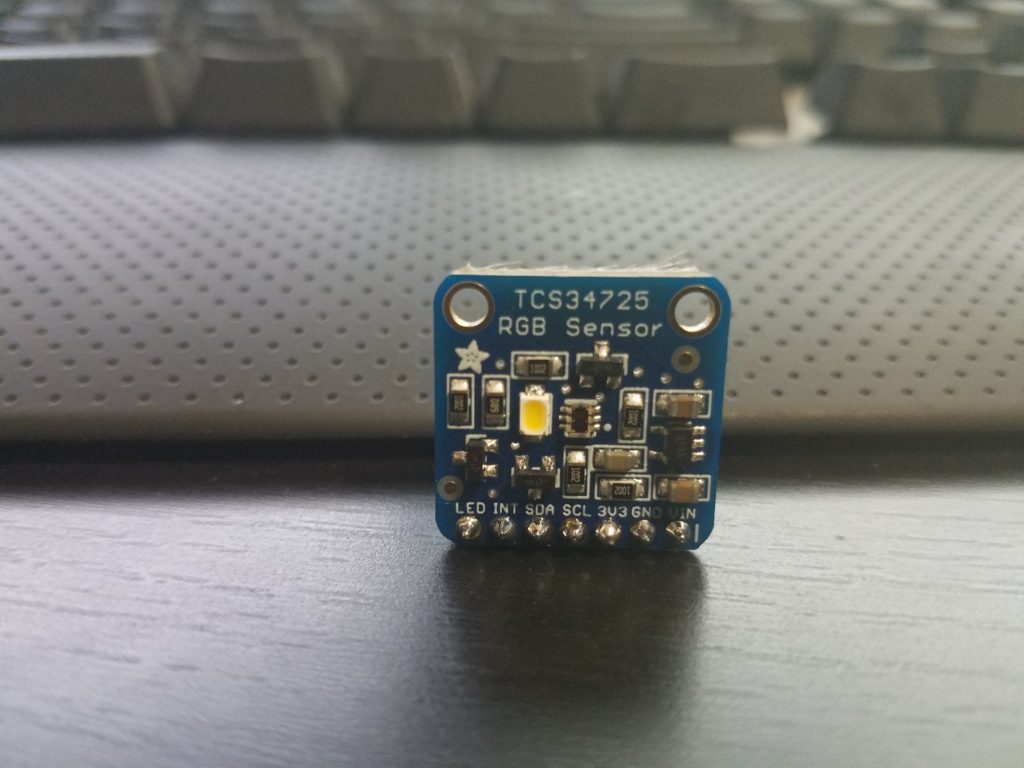
The process for soldering the board is standard. Typically you are given a row of pins that is one too long. Break one pin off and place the rest (connected) in a bread board. If you put the board on the pins you may notice it leans on the other side. You can use the extra pin to prop up the opposite side through the mounting hole.

Since the spacing is close, I would recommend testing for shorts with your multi-meter.

Library
Within the Arduino IDE you can use the wizard to install the TCS34725’s library. Search for TCS34725.
You can manually obtain the files here: Adafruit TCS34725 Library

Findings
It is relatively easy to get the circuit working. The complexity is introduced based on your application and fine tuning. Some of the concerns I have when working with this passive sensor are the speed and precision.

Ways to get around the limits of an individual sensor, assuming that’s where the bottle neck is occurring, is to increase the amount of sensors and/or microcontrollers in your project. Somes ways to accomplish this is with multiplexing or creative coding or using brute force. Some sensors behave better than others in groups. These sensors have a static I2C address, and that will cause issues unless you multiplex physically or through code.

For this color sensor, the exposure time affects the brightness read. This is controlled by a variable:  TCS34725_INTEGRATIONTIME_50MS.
50MS is the exposure time for the reading. All other things being the same, lowering the exposure time reduces the values or intensity of the RGBC readings.

If you want the current exposure time but twice the rate of readings, you may consider introducing a second sensor. You can keep them on pace by assigning them to the rise and fall of the clock cycle. I have not tested this for these chips though.  However the speed of these sensors would not work well with most speed dependent applications like video games and instruments.

Example Uses
Some uses for these color sensors are color testing output of color reprographics devices. In fact color testing in general would be a obvious strong point for this sensor, from paint jobs to adjusting light based on the current ambient level.

As far as tangible applications. One could design a device that requires users to insert objects into it. So inserting different colored key cards to be read by the scanner can trigger different events. The enclosure would minimize the amount of light bleed from the environment and the on board illuminator would allow for the color to be read inside.

Another tangible example would be to use the sensors as a “conductor”. What I mean by that is, if you have a translucent enclosure and want to have no visible wires between a button and an open section. You can have a grid of buttons with LEDs that correspond to a unique color for each. Rather than having 18+ wires for a 3×3 grid going through the enclosure. You can mount a color sensor on the opposite end and have it determine the button press based on the color of each one.

Strength and Weaknesses
Strengths

  • Reads RGBC values individually
  • Filters IR light so the values read are closer to actual human sight
  • Relatively low power draw.  Scaling potential.
    • Active = (235 – 330μA)
    • Waiting = (65 μA)
    • Sleep = (2.5 – 10μA)

Weaknesses

  • Small effective range. Up to 4 inches.
  • Relatively slow. Speed affects quality of reading.
  • Static I2C addresses.

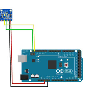
Example Circuit Schematic
Microcontroller Code

Citations:
Adafruit TCS34725 Library

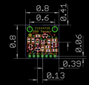
Breakout Board Fabrication Print

Manufacturer’s Product Site – AMS
Splitter Glove – MIDI Controller (in progress)

The second project for Tangible Interactions was to create a MIDI controller.
I was in NIME last semester and created a final project which was a MIDI controller. The controls were very much intangible, which I partially addressed somewhat in its design. However the controller had a bit more to go to reach my final vision. I wanted to move beyond the limits of the technical flashlights and LEDs I initially used to play it.

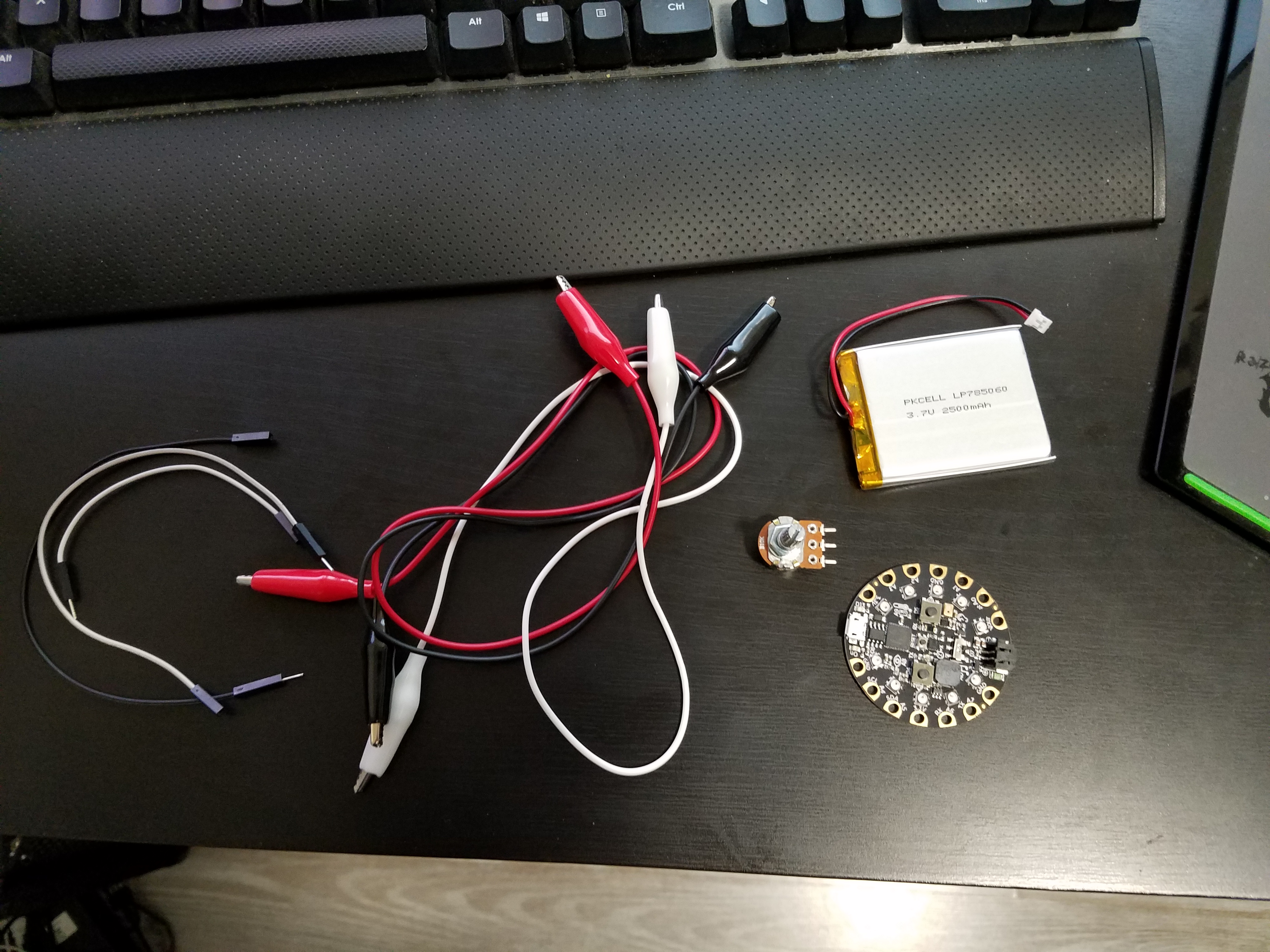
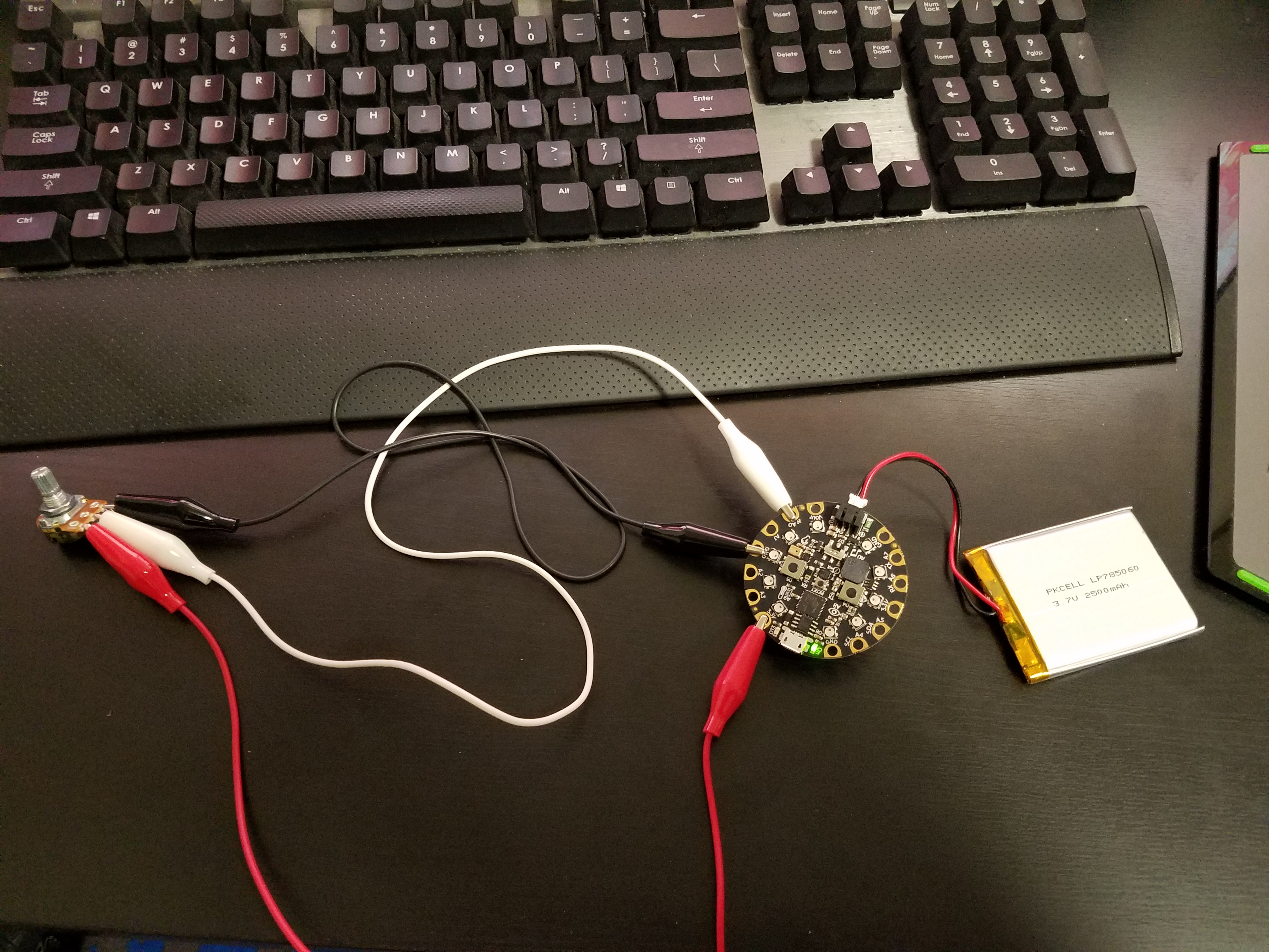
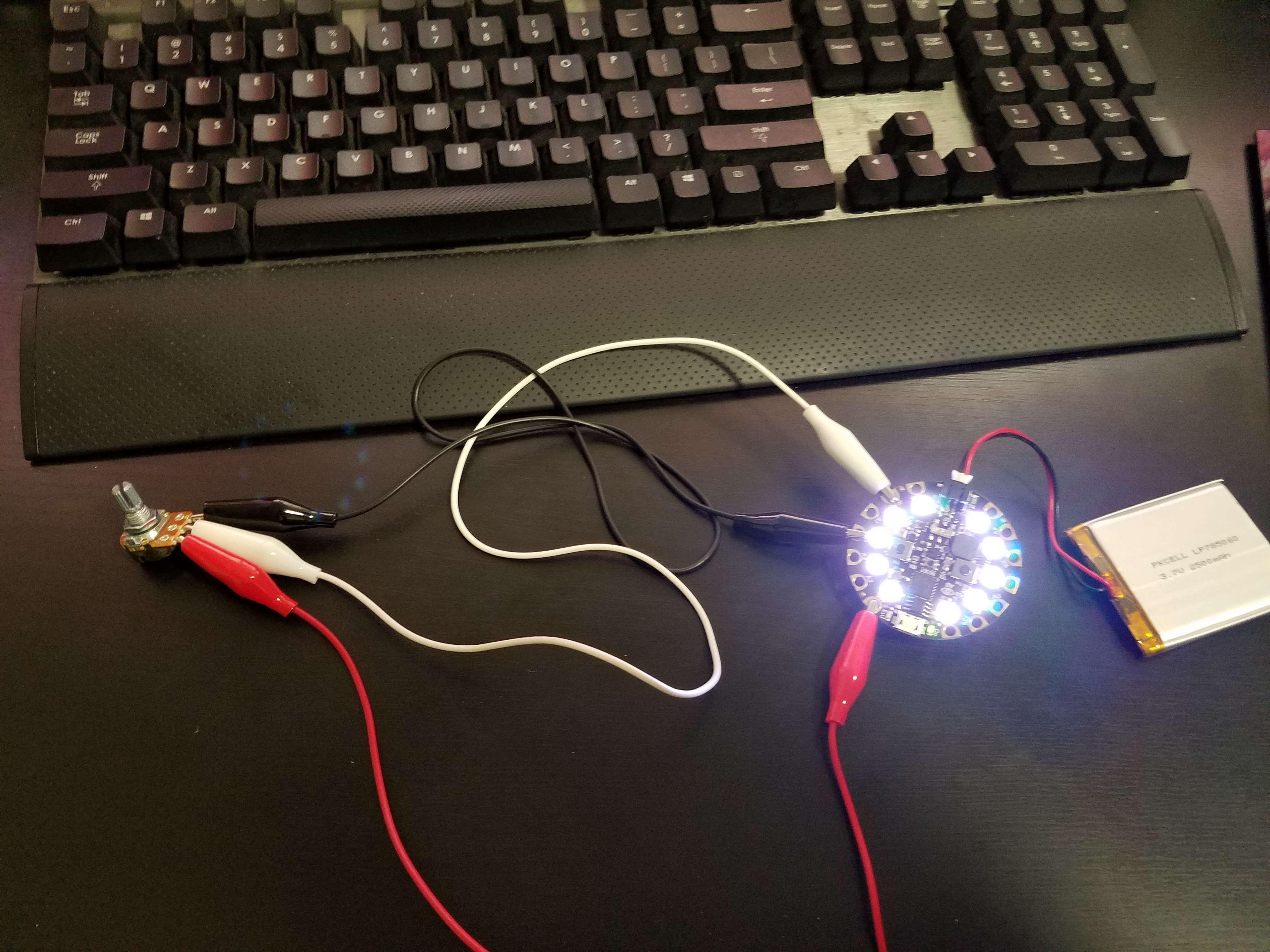
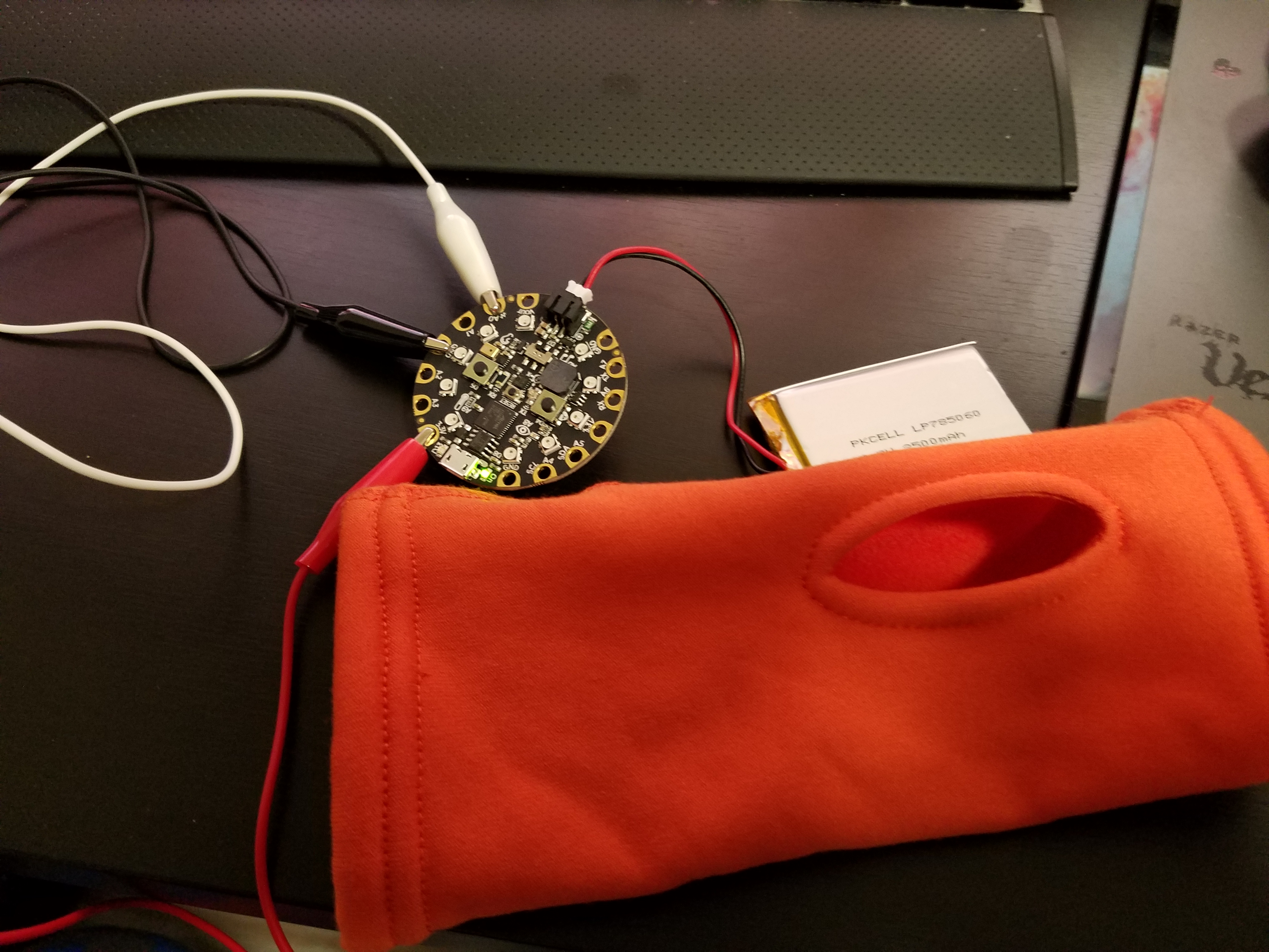
My goal was to add tangible elements to the controller’s interface by using wearable lights and a physical control for the blinking and on/off functionality. The MIDI notes are triggered when light hits the sensor and off when the light level falls below a threshold value. By being able to control the blink rate with a potentiometer, I added a tangible element to an intangible interface.

There are more thing I could modify to increase the preciseness of the controller.  But I have to consider how I want it the experience to evolve.

Synthetic Architecture 02 – Anatomy of Space

I picked waiting as my simulation experience. As humans we are accustomed to things happening in our lifetime. However nature doesn’t conform to our notions of immediacy.

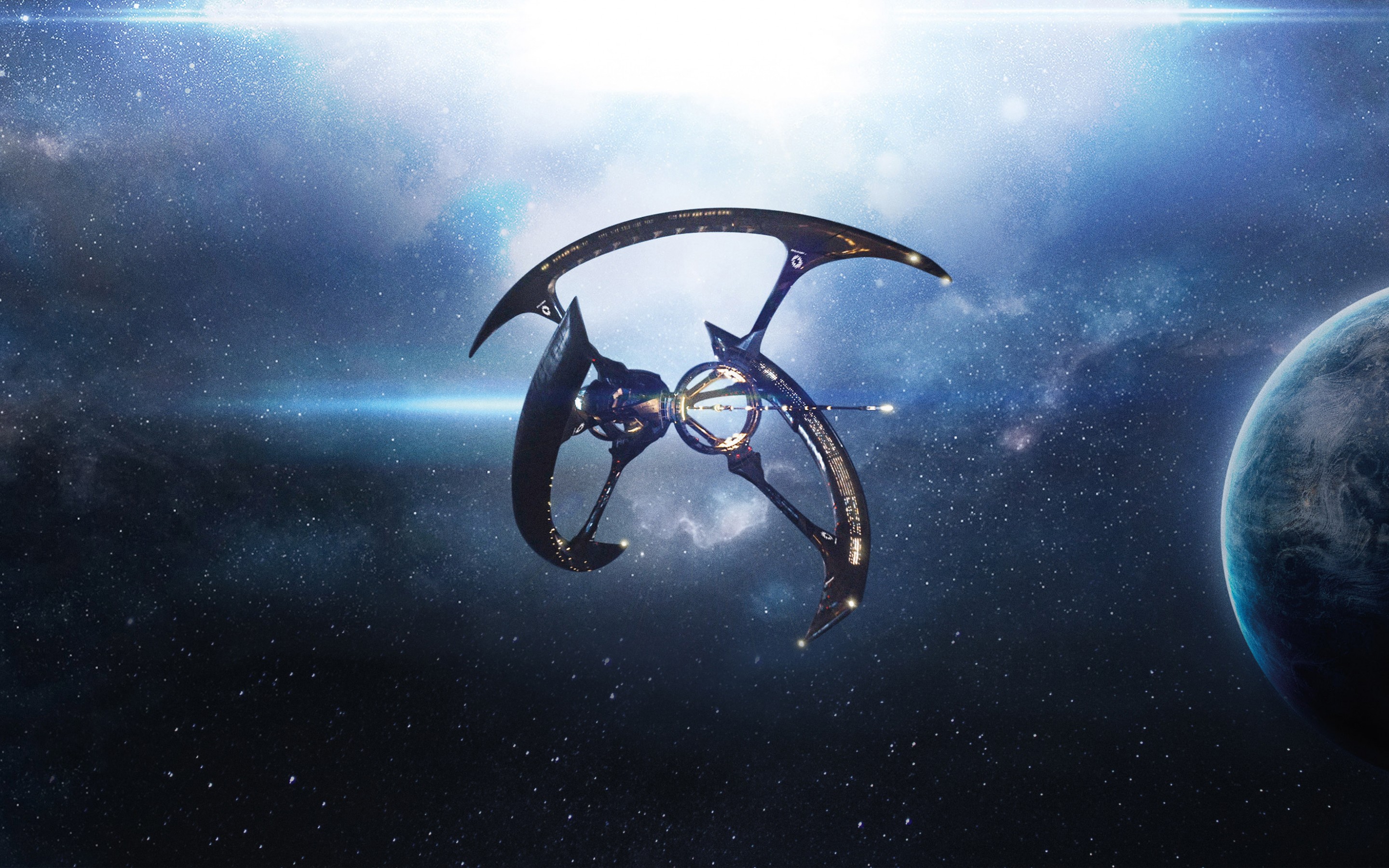
I decided to demonstrate waiting by creating a simulation of travelling through space. The scale would be extreme because the user will not have much interactions in the confined space. As a juxtaposition there will be astronomical events occurring at a great distance visible to the user.


Worlds On A Wire – HW Week 02

For this assignment I jumped into Steam with my Oculus Rift headset, which is a really great and new feature Valve decided to add. I think it’s akin to them adding native support for the Sony Dualshock 4 controller. They have been more inclusive with their platform over the last couple of years.

The experience in the Lab was great. Everything looked better then when I first tried it 2 years ago for some reason. As I mentioned in the previous post, being able to focus at home adds a lot to the immersive experience. I have to say even doing the Steam tutorial, I forgot how to “travel.” So I was stuck in the opening Lab scene for a while.., even after I teleported once. I didn’t realize it was not so rigid and I could teleport again in the same region to get closer to the orb.

As for the Unreal hero shots. I have been combining shapes and assets together. It did take me a while to figure out the importing assets workflow. I feel really restricted in the UE environment. The pain points for me is the navigation of the view port, the snapping of values and not being able to “model geometry” at a higher level that I’m used to. A part of it is learning their modeling tools more. But I have to say I am enjoying the UE interface.

For my scene I created a flat world with shapes and objects. I think it resembles some sort of ruins. The main character is the ice elemental guy.

Winter Show 2016

I did a Hail Mary play and a complete gamble by ordering some uber IR sensors on Friday, having same day delivery for $30 with no idea if these will work how it needed to. The gamble paid off, and while I am poorer for it, we were able to have a better functioning sensor array for the show.
Though that was just one of many hurdles we faced before and during the Winter Show including Melissa building up a chassis we consulted with Chester on. Melissa and I had an awesome time even though we were a bit stressed with all the tinkering we needed to do to ‘right’ the ship.We were approached by some interested people who will pay us half a billion dollars to make it for their bathrooms!!

Videos soon.

Final Project Pre-Show Update


The third prototype:
For our final physical computing class, we really wanted to get four sensors working. Unfortunately the delays that we used to send and receive ultrasonic pings clogged up the entire system. The current state of our code only allows for two sensors. However, we made progress in terms of getting one sensor to play multiple notes, as seen in this video:

[youtube https://www.youtube.com/watch?v=Mh-9GeeujMs&w=560&h=315]

We’re still not sure the best way to “zhush” it up, other than by adding painting the pvc pipe? We still need to figure out the kind of enclosure we want to use for our circuit, and bring some dignity to the sad plastic basin. We also need to get a working system without using four different arduinos. But the prototype works!

Final Project Update

STATUS UPDATE:
Melissa and I ran some more tests with lasers and water streams at school and individually at home. Unfortunately we are still fine tuning our alternative light and sensor interface that will trigger the MIDI notes.

circuit-one-note
This is our first attempt at a MIDI output circuit.

[youtube https://www.youtube.com/watch?v=S9DfrA_zg9s]
This is us using the stock MIDI code from Arduino’s site. We are running the Arduino through a MIDI jack to a MIDI/USB converter and then into a soft synth.

[youtube https://www.youtube.com/watch?v=N_N5kUX2LUY]
This is one of our laser tests. I think it’s a cool effect but if we do use it, it will be more for aesthetic purposes.

We met again yesterday to test out our pump and PVC pipes for the fabrication part of the project. I think we are in a good place but we still have to catch up on the deliverables. Luckily I took off next week to focus on getting this completed.

DELIVERABLES (in progress):

Concept & Brainstorming (DRAFT)

Melissa and I decided to work together for the final project. We are working on creating a water instrument. The main interface will be a water fall or water sheet.20161110_111227

I am thinking about the pros and cons or it being a midi controller versus a function generator.

+Post Final Project Concept discussion (11/12/16):
We had a very productive demonstration of our water synth project. Here is a video of how we simulated our concept.
[youtube https://www.youtube.com/watch?v=SwhLLJ6mam0]

We received a lot of great feedback from our classmates and of course our Instructor Benedetta. After the testing we knew we had a good idea to proceed with and were confident that it would be something we could pursue.

After the demo we met to test our idea. We wanted to have several lasers travel through a waterfall. Unfortunately that is not easy to do and the results were not promising. We were able to get the laser to travel along a stream but it became increasingly difficult to get a projection the higher we went.

DELIVERABLES (WIP)